
Field Data Report
Photovoltaic-Thermal (PVT) Modules as Sole Heat Source for Brine-to-water Heat Pumps
Contents
Authors:
- Dipl.-Ing. Friedrich Ohrt, Dr. Jiri Springer, Dr. Wilhelm Stein; Sunmaxx PVT GmbH
- M. Sc. Simon Büttgenbach; PVT-Expert
- Dr. Andreas Bohren; SPF Institut für Solartechnik
Abstract
Photovoltaic-thermal (PVT) modules enable the simultaneous generation of electricity and heat from roof and ground-mounted areas, thereby significantly increasing energy yield per unit of area. Based on field data from real-world installations and accompanying simulations, this paper examines the operation of PVT collectors as the sole heat source for brine-to-water heat pumps during both winter and summer periods.
The focus is on uncovered, uninsulated PVT collectors (WISC, wind and infrared sensitive collectors) featuring a flat absorber fully bonded to the PV laminate, such as the PX-1 model manufactured by Sunmaxx. The system is based on highly efficient thermal management technology developed for the automotive industry. This enables a high overall efficiency while effectively cooling the solar cells. In addition, the module extracts heat from solar and long-wave infrared radiation as well as from the ambient air. The collectors are also characterized by a simple construction that allows for easy and reliable installation on standard PV mounting systems, thereby reducing system complexity and costs.
The measurements demonstrate that stable source temperatures for the heat pump can be achieved even in winter, including under monovalent operating conditions. Under solar irradiation, source temperatures are often significantly higher than the ambient temperature, while in the absence of irradiation they remain only a few kelvin below ambient temperature. The PVT systems investigated were sized between 2.0 and 4.5 m² per kW of heat pump heating capacity (at B0/W35). Even during the cold heating season of 2025/26, a seasonal coefficient of performance (SPF) above 4.5 was achieved under monovalent operation with a system sizing of 2.8 m²/kW.
Introduction
Photovoltaic-thermal (PVT) collectors enable the use of roof and ground-mounted areas for the simultaneous generation of electricity, heat, and cooling. This significantly increases energy yield per square meter and makes an important contribution to sector coupling in the building sector. In PVT modules such as the Sunmaxx PX-1, the uncovered and uninsulated thermal absorber (WISC, wind and infrared sensitive collector) is fully bonded directly to the PV laminate. This design achieves an optical efficiency of approximately 60%. As a result, the Sunmaxx PX-1 is currently the PVT WISC collector with the highest optical efficiency, achieving an overall efficiency (thermal and electrical) of more than 80% % (see Figure 1).
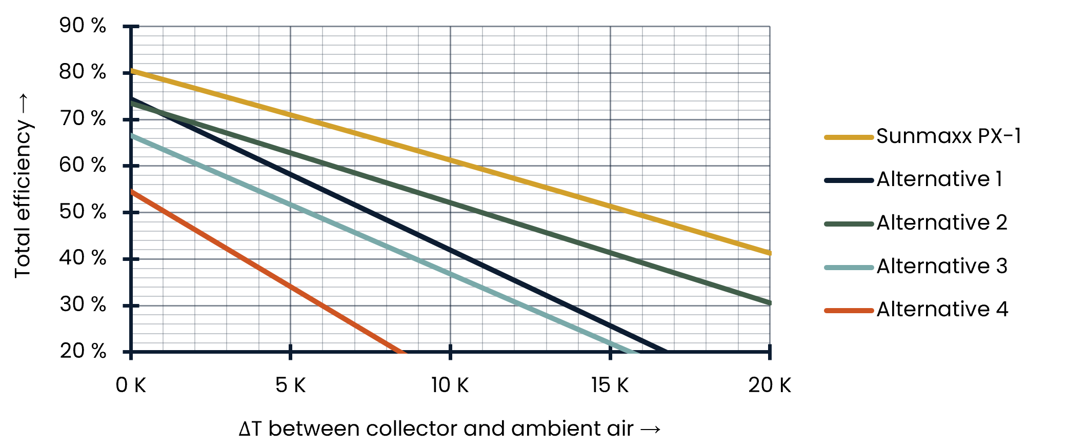
Figure 1: Efficiency curves of PVT WISC collectors
At the same time, the full-surface absorber provides effective cooling of the solar cells. Due to the temperature-dependent performance characteristics of PV modules, this can result in additional electrical yields of up to 10% compared with conventional PV systems. Figure 2 shows the uniform heat extraction across the entire module surface.
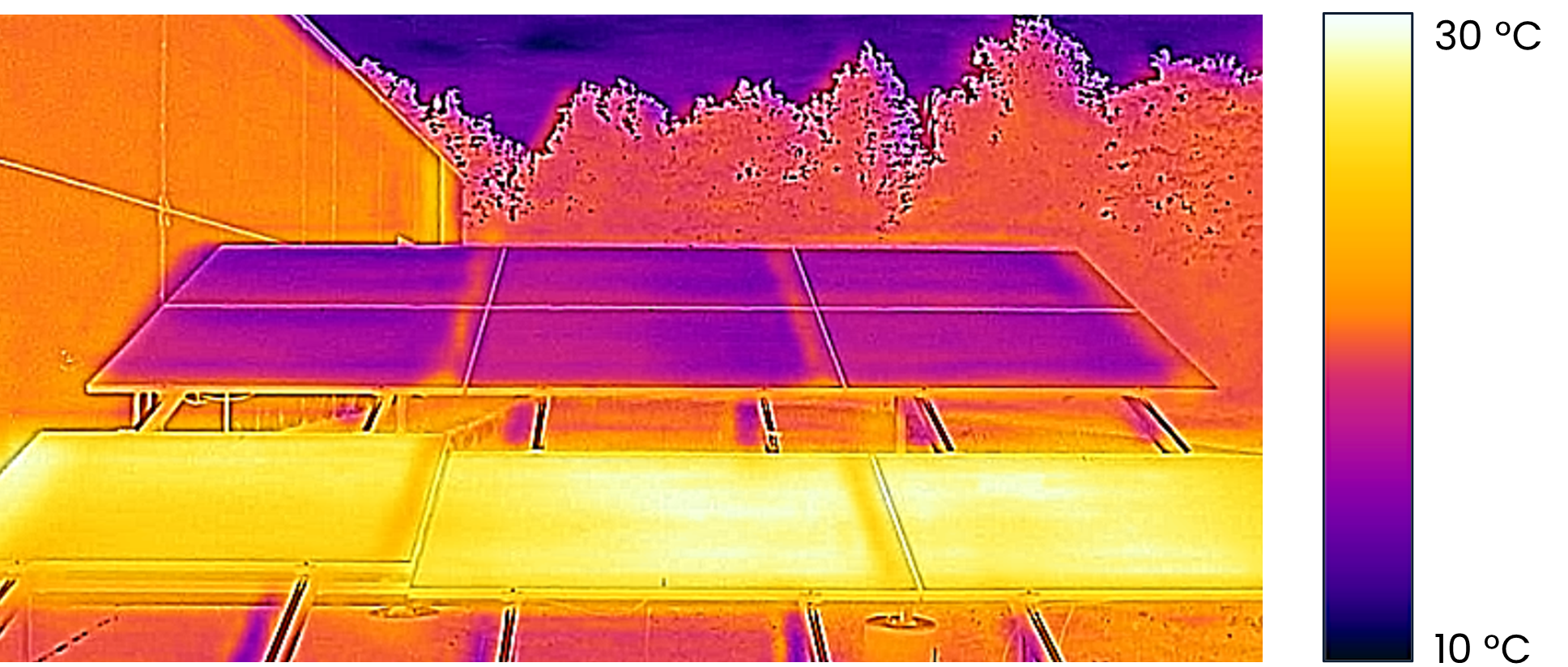
Figure 2: Thermographic image during heating operation
Top: Connected modules in operation. Bottom: Unconnected modules as a reference
Heat can also be extracted from the ambient environment via the absorber on the rear side of the PV laminate (WISC), even in the absence of solar irradiation. This enables this type of collector to serve as the sole heat source for heat pumps (HPs). [1, 2, 3, 4]. This operating mode is referred to as monovalent operation (or monoenergetic operation when a backup electric heating element is used). In contrast, bivalent systems use additional heat sources or seasonal thermal storage systems, such as borehole heat exchangers. [5, 6, 7, 8, 9].
The data presented here demonstrate that PVT enables efficient heat pump operation even without additional heat sources. A key factor is the utilization of convective heat gains as well as long-wave infrared radiation received through the front surface. This is made possible by the full-surfaced, thermally conductive connection between the absorber and the module. Without such a connection – i.e., if the thermal absorber is not directly bonded to the laminate – these heat gains cannot be utilized. For the effective utilization of convective heat transfer, the connection between the heat exchanger and the brine circuit is crucial. In flat absorbers, the ambient air is directly coupled to the brine via a thin metal sheet. If the heat exchanger area is increased relative to the collector gross area, for example by using fins, the heat exchanger is not directly exposed to the brine flow. This introduces additional thermal resistances in the transfer of heat from the ambient air to the heat transfer fluid. Furthermore, the enlarged heat exchanger area cannot be directly compared with the heat exchanger area of flat absorbers. In finned structures, for example, convective heat transfer does not scale linearly with the geometrical heat exchanger area; instead, the effective heat transfer increases at a significantly lower rate.
In cooling mode, heat is dissipated convectively to the ambient environment via the rear side. In addition, heat is radiated from the front surface of the module toward the cold night sky. These PVT modules can therefore also serve as a heat sink for both passive and active cooling [10, 11].
The lightweight module design, with the absorber contained within the frame, enables easy installation on standard PV mounting systems while keeping the additional roof load low. Furthermore, the use of plug-in connectors makes installation times only slightly longer than those of conventional PV systems. Scalable mass production enables low manufacturing costs, while standardized quality control ensures consistently high product quality. With a pressure drop of only 29 mbar across the module, up to 24 modules can be connected in parallel to a common manifold. This further helps reduce installation time and system complexity.
Furthermore, the flat absorber design is insensitive to icing and does not require any specific airflow through the air masses behind the modules. Depending on the module exposure and the design of the absorber and mounting system, airflow can be significantly impeded in real-world conditions [12]. Convective heat gains in alternative module types with an enlarged heat exchanger area on the rear side, for example through the use of fins, are therefore also limited under such conditions. The following section presents representative field data from the large number of installations already deployed in order to reflect real-world operating conditions. For each installation, the location, installation type, and PVT system sizing in relation to the heating capacity of the installed heat pump at B0/W35, expressed in m²/kW, are provided.
The heat pump’s performance characteristic determines the heat demand placed on the PVT system. Depending on the ambient conditions and the available PVT area, this results in a corresponding source temperature. The heat pump’s performance characteristic provides a stabilizing effect in this regard: if the source temperature decreases due to an increased demand for heat pump capacity, the heat pump’s output decreases as a result of the lower COP, thereby stabilizing the source temperature (see figure 3).
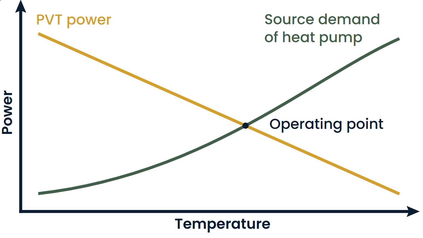
Figure 3: Schematic performance curves of the heat pump and PVT system
The critical threshold is the minimum evaporator inlet temperature permitted by the heat pump. If the source temperature falls below this limit, the heat pump must shut down. For typical Central European climate conditions, heat pumps capable of operating at temperatures of −15 °C or lower are recommended [13]. With a larger PVT array, both a greater surface area for radiative heat gains and a larger effective heat exchanger area for convective heat gains can be utilized. As a result, the source temperature is correspondingly higher, increasing the efficiency of the heat pump. As a rule of thumb for sizing systems with flat absorbers, a PVT area of approximately 4 m² per kW of heat pump heating capacity at B0/W35 is recommended. This sizing value has been implemented in publicly accessible reference installations using both collectors with enlarged heat exchanger areas and collectors with full-surface absorbers.
Utilization of Direct Solar Irradiance
Under solar irradiation, the brine temperatures in the PVT module rise significantly above the ambient temperature due to its high optical efficiency. The flat absorber design and the associated low fluid volume give the system a high dynamic response, directly converting solar irradiation into high source temperatures.
As a result, on sunny winter days, the heat pump coefficient of performance (COP) is significantly higher than that of comparable air-to-water heat pumps (air HP). The system also enables effective (intermediate) regeneration of seasonal thermal storage systems. Through both mechanisms, the electricity demand for heating –and consequently overall winter electricity demand – can be significantly reduced.
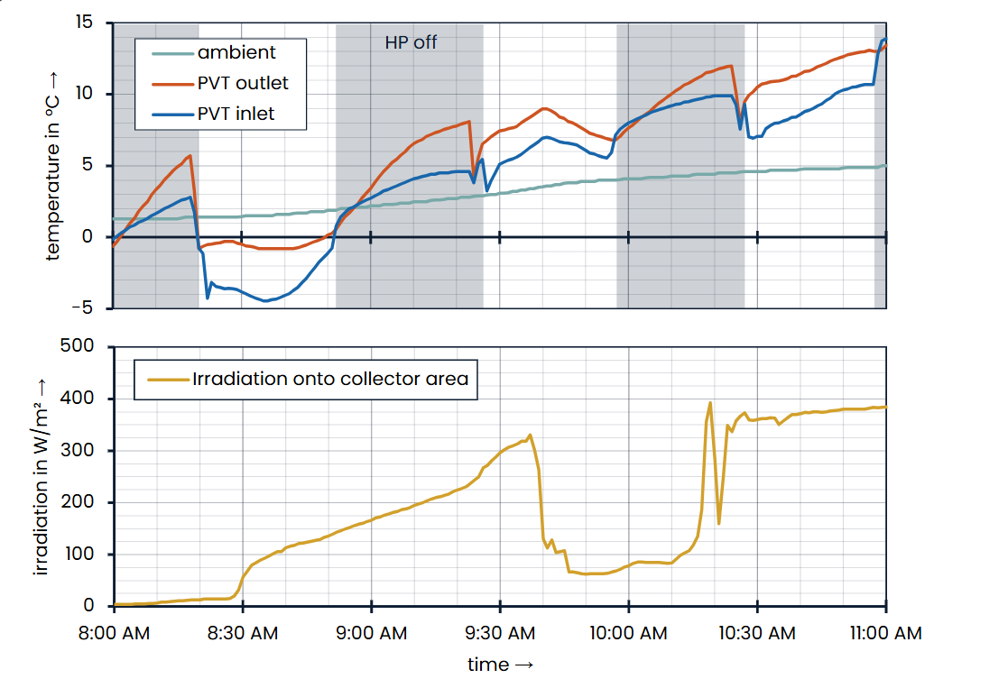
Figure 4: Representative sunny winter day (18 Dec. 2025 | Ottendorf-Okrilla | ground-mounted | 4 m²/kW)
Figure 4 shows a representative sunny winter morning at a ground-mounted installation during the 2025/26 winter season. At sunrise (8:30 a.m.), the source temperature approaches the ambient temperature (approximately 1 °C). It then rises above ambient, reaching around 8 K above the ambient temperature at an irradiance level of approximately 400 W/m² (a source temperature of 13 °C at an outdoor temperature of 5 °C at 10:50 a.m.). During an intermittent period of cloud cover (9:40-10:20 a.m.), the source temperature decreases slightly but, due to the system’s thermal inertia, does not fall below the ambient temperature. This behavior highlights the advantage of the full-surface, direct thermal coupling of the absorber to the PV laminate.
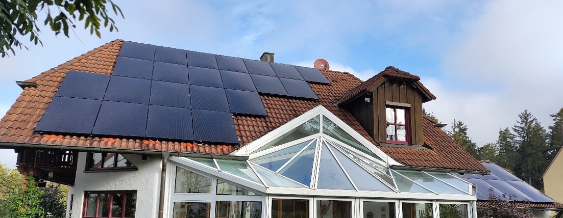
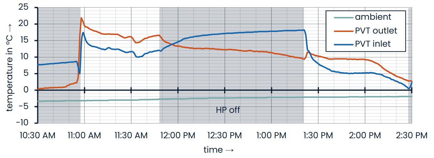
Figure 5: Sunny winter day (13 Jan. 2025 | Regensburg | pitched roof | 4.5 m²/kW)
Figure 5 illustrates this advantage at a PVT installation on a pitched roof, with an outdoor temperature of −1 °C during the 2024/25 winter season. In the morning, with good solar irradiation on the module plane, the source temperature reaches 17 °C at 11:20 a.m., which is 18 K above the ambient temperature. In the afternoon, it initially remains 11 K above ambient at 10 °C (1:20 p.m.). As the modules become shaded due to the low solar elevation angle, the source temperature subsequently approaches the ambient temperature (2:30 p.m.).
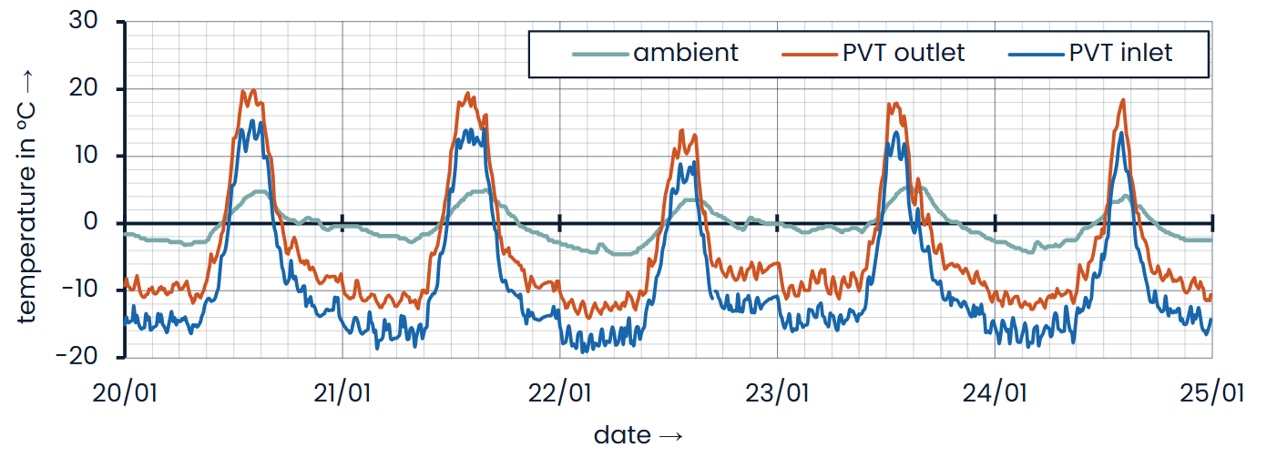
Figure 6: Sunny winter week (2026 | Stuttgart | pitched roof | 3 m²/kW)
Figure 6 shows similar behavior during a sunny winter week in early 2026. During the day, source temperatures of 15 to 20 °C are reached at ambient temperatures of around 5 °C. By scheduling heat pump operation during these periods, similar to PV self-consumption optimization, efficiencies exceeding those of ground-source heat pumps with borehole heat exchangers can be achieved. In addition, during these sunny hours, the heat pump can draw its electrical energy directly from the electricity generated by the PVT system. The system is therefore not only highly efficient but also (partially) energy self-sufficient. This has a positive impact on the building’s overall winter electricity consumption.
Operation Without Direct Solar Irradiation (Nighttime Operation)
In the absence of direct solar irradiation, the PVT module gains heat primarily through convection from the ambient air. As a result, the source temperature drops a few kelvin below the ambient temperature. Compared with an air-to-water heat pump, it should be noted that heat transfer between the brine and refrigerant is significantly more efficient than between air and refrigerant. Consequently, the evaporation temperatures of PVT systems can remain higher even at slightly lower source temperatures. The temperature difference between the PVT system and the ambient environment is determined by two factors. On the one hand, effective wind flow enhances heat transfer and therefore increases the PVT temperature. On the other hand, the full-surface absorber is also sensitive to diffuse short-wave and long-wave (infrared) radiation. Corresponding incoming or outgoing radiation therefore also affects the source temperature, independently of wind conditions.
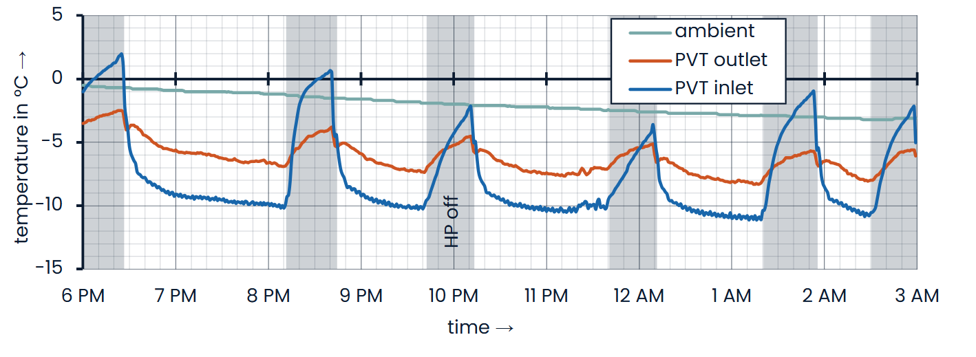
Figure 7: Low-wind night (18–19 Jan. 2025 | Regensburg | pitched roof | 4.5 m²/kW)
Figure 7 shows nighttime data without these beneficial factors. The wind speed, according to a nearby weather station, was below 1 m/s, and there was no daylight – and therefore no diffuse solar irradiation – throughout the entire period. These conditions represent the “worst-case” scenario and thus the design point of the PVT system. The source temperature is approximately 4 K below the ambient temperature. The heat pump regulates the flow rate to maintain a 3 K temperature differential in the brine circuit.
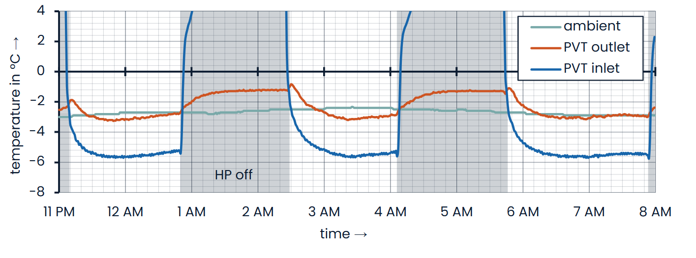
Figure 8: Windy night (18–19 Jan. 2025 | Regensburg | pitched roof | 4,5 m²/kW)
Figure 8 demonstrates the source temperatures of the same installation during a windy night. The average wind speed was 4 m/s, with gusts exceeding 10 m/s. The PVT outlet temperature reaches −3.0 °C, almost matching the ambient temperature of −2.7 °C (12:30 a.m.). At a wind speed of 3 m/s, the temperature difference is likewise less than 1 K (3:30 a.m.). Toward the end of the night, the source temperature reaches the ambient temperature of −2.9 °C (7:30 a.m.). At this time, the wind speed has increased again to more than 4 m/s, while diffuse and long-wave radiation from the approaching sunrise are already beginning to contribute as well.
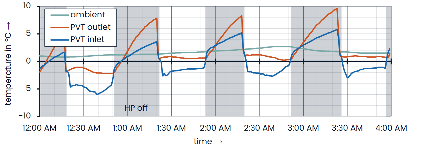
Figure 9: Nighttime operation (18 Dec. 2025 | Ottendorf-Okrilla | ground-mounted | 4 m²/kW)
Figure 9 shows the nighttime operation of a ground-mounted installation in December 2025. The source temperatures are between 1 and 3 K below the ambient temperature.
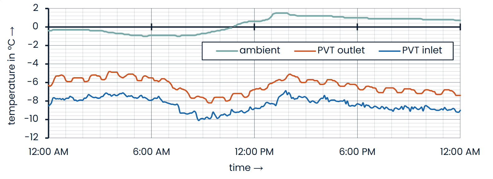
Figure 10: Winter day without sunshine (26 Jan. 2026 | Essen | pitched roof | 2.8 m²/kW)
In figure 10, the temperature profiles of a relatively small PVT system (2.8 m²/kW) are visualized. The modulating heat pump operates continuously at outdoor temperatures around 0 °C. The source temperature ranges between −5 and -7 °C, approximately 4 to 7 K below the ambient temperature. Despite the relatively small system size, stable and efficient operation is ensured because the selected heat pump is capable of operating with source temperatures down to −25 °C.
Winter Operation with Snow
During the heating season, stable and efficient operation is particularly important under conditions of snowfall and icing. Icing of the rear-side absorber can occur when the brine temperature falls below 0 °C and below the ambient dew-point temperature. If sufficient humidity is present, condensation forms on the absorber and may freeze. Especially during snowfall or sleet, collector designs with enlarged surface areas can promote the formation and accumulation of an ice layer. This ice layer must be removed through defrosting to allow continued operation, which is not only energetically demanding but also technically complex.
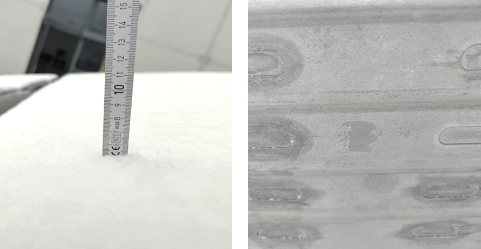
Figure 11: Ice layer under snow cover during continuous operation (3 Jan. 2025 | Ottendorf-Okrilla)
With flat absorbers such as those used in the Sunmaxx PX-1 module, there is little potential for the formation of such an ice layer. The ice layer that does form is only a few tenths of a millimeter thick and has little impact on heat transfer or the operation of the PVT system. Figure 11 shows this ice layer, which formed under complete snow cover (>5 cm) and continuous heat pump operation. Consequently, complex defrosting processes, such as those required for air-to-water heat pumps, are generally not necessary.
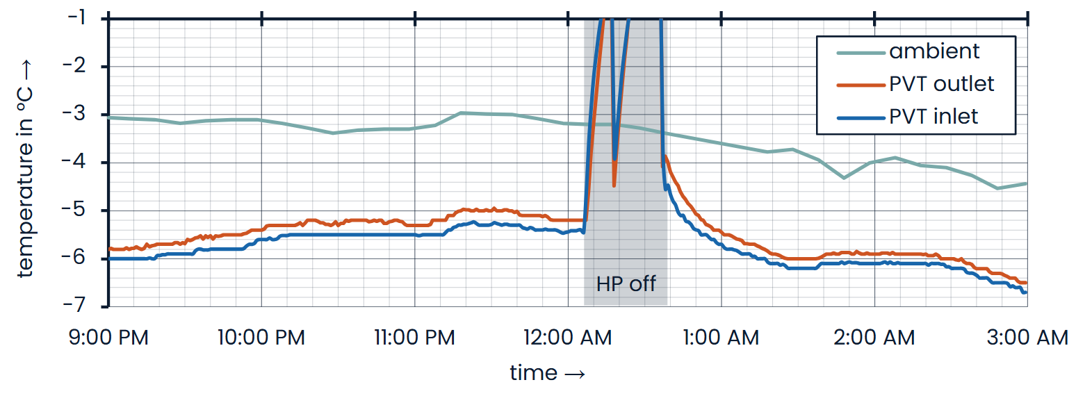
Figure 12: Snow-covered night (13–14 Jan. 2025 | Ottendorf-Okrilla | ground-mounted | 4 m²/kW)
Figure 12 shows the nighttime temperature profile under snow-covered conditions. It is the same installation as the one shown in figure 9. Several centimeters of snow covered the modules throughout the night. The source temperature was 2 to 3 K below the ambient temperature, thus remaining in a similar range to that observed under snow- and ice-free conditions.
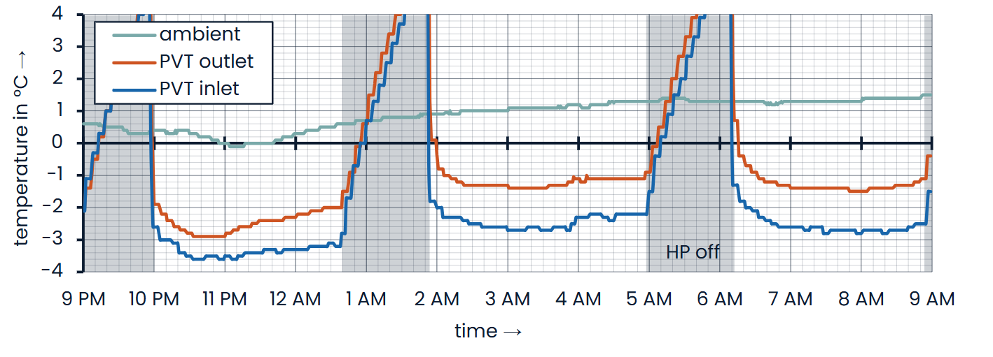
Figure 13: Snowy night (30–31 Jan. 2026 | Regensburg | pitched roof | 4.5 m²/kW)
Figure 13 shows a snow-covered night at the installation presented in figure 7 and figure 8. The temperature difference between the ambient temperature and the PVT outlet temperature is likewise 2 to 3 K, thus remaining within the same range as under snow-free conditions. Operation as a heat source for a heat pump is therefore not impaired either by snow cover on the modules or by the minimal layer of ice forming on the rear-side absorber.
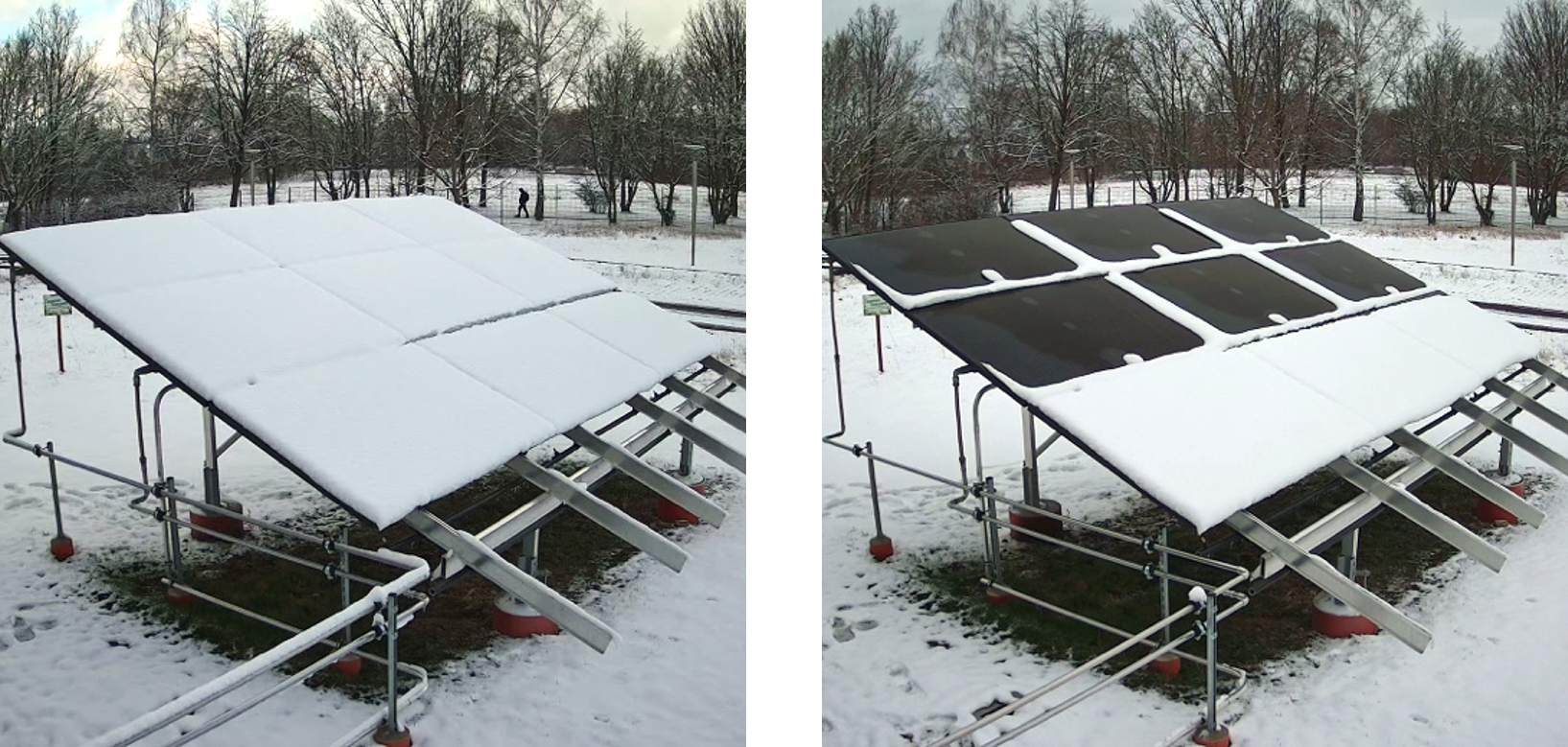
Figure 14: Snow melting (bottom modules disconnected | 14 Feb. 2025 | Ottendorf-Okrilla)
However, snow cover can significantly reduce the electrical yield of PV systems, particularly in regions with heavy snowfall. In PVT modules with a full-surface thermal connection between the heat exchanger and the PV laminate, the snow cover can be efficiently melted away (see figure 14). The module surface is then available for electricity generation again—a major advantage, particularly during the winter months when the supply of renewable electricity is low. To achieve this, heat is transferred to the module via the brine circuit, similar to cooling operation. This can be accomplished either by reversing the hydraulic flow or, in heat pumps capable of reverse operation, by reversing the refrigerant cycle. As a result, the snow cover either slides off or melts. The technical and economic feasibility of this approach has been demonstrated, among other studies, in the award-winning paper “Maximizing Winter Electricity Generation with Snow-Free PVT Modules” (original title "Winterstrom maximieren mit schneefreien PVT-Modulen") [14]. The additional electrical yield achieved through snow melting averages 34% in regions with heavy snowfall and can reach up to 61%, depending on the location. The thermal energy required is approximately 1.1 kWh/m² for a snow cover of 10 cm. When using a heat pump in reverse operation with a seasonal performance factor of 5.5, the corresponding electrical energy demand is only around 0.2 kWh/m². If the source energy required for snow melting is drawn from a buffer storage tank, this energy must subsequently be regenerated and stored again after the snow has been removed.
Dimensioning and System Efficiency
The system data presented so far are derived from PVT heat pump systems with different configurations. The PVT area was sized between 2.8 and 4.5 m² per kW of heat pump heating capacity at the nominal operating point B0/W35. As a general rule of thumb, a PVT area of approximately 4 m²/kW is recommended, although the optimum system size is always project-specific. The sizing of the PVT system therefore represents a design parameter within the overall system configuration [15]. As shown in figure 3, the source temperature is established as the operating point at the intersection of the heat pump and PVT performance curves. The thermal output of the PVT array scales almost linearly with its area. Accordingly, a larger PVT array enables a higher source temperature and thus more efficient heat pump operation.
Since heat pumps also provide higher heating capacity at higher source temperatures, the heat pump’s coverage ratio can increase with a larger PVT system. Depending on the heat pump’s permitted minimum evaporator inlet temperature, correctly sizing the PVT system can also prevent shutdown periods caused by an excessively cold heat source. This minimizes the operating time of an auxiliary heat generator, such as an electric heating element. Overall, increasing the size of the PVT system therefore improves overall system efficiency.
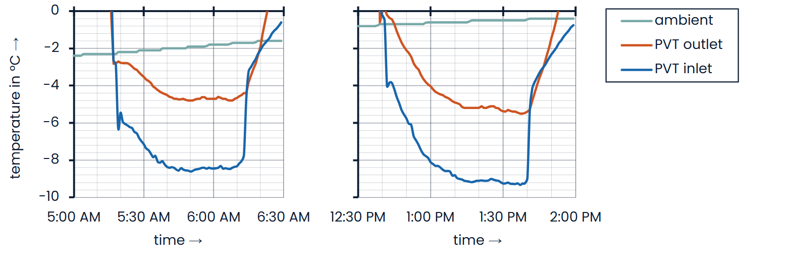
Figure 15: Variation in PVT system sizing (9 Jan. 2026 | Ottendorf-Okrilla | ground-mounted).
To illustrate the impact of system sizing, the module array of an operating installation was temporarily reduced by half on a cloudy day. Figure 15 shows the measured temperature curves. In the morning (5:20–6:15 a.m.), the system operated at the standard sizing of 4 m²/kW. Under steady-state conditions, the source temperature was 2 to 3 K below the ambient temperature. After switching to 2 m²/kW, this temperature difference increased to 4 to 5 K (12:40–1:40 p.m.). Halving the module area therefore resulted, as expected, in approximately a doubling of the temperature difference between the heat source and the ambient environment.
The influence of system sizing on overall system efficiency was also investigated through simulation-based analysis. Simulations were carried out using Polysun with varying PVT array sizes. The model considered a two-family house in Dresden equipped with underfloor heating (35/30 °C) and a domestic hot water demand for eight occupants (50 °C, with daily thermal disinfection at 60 °C). Figure 16 shows the corresponding Polysun system schematic. The PVT array size was varied between 2 and 6 m²/kW, while all other parameters remained unchanged.
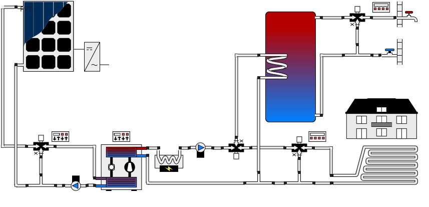
Figure 16: Polysun system schematic for calculating system efficiency at different system sizes
Figure 17 demonstrates the results of this simulation. With the standard sizing of 4 m²/kW, the heat pump achieves a seasonal coefficient of performance (SCOP) of just under 4.5. The share of the electric heating element is only 1%. This represents the proportion of the total heat generated that is supplied by the electric heating element as an auxiliary heat generator. The PVT system can also directly provide part of the heat pump’s electrical input. Without battery storage, the system achieves an energy self-sufficiency rate of 37%. If only electricity drawn from the grid for heat generation is considered in the energy balance, the system seasonal coefficient of performance is 6.8 (PV-SCOP).
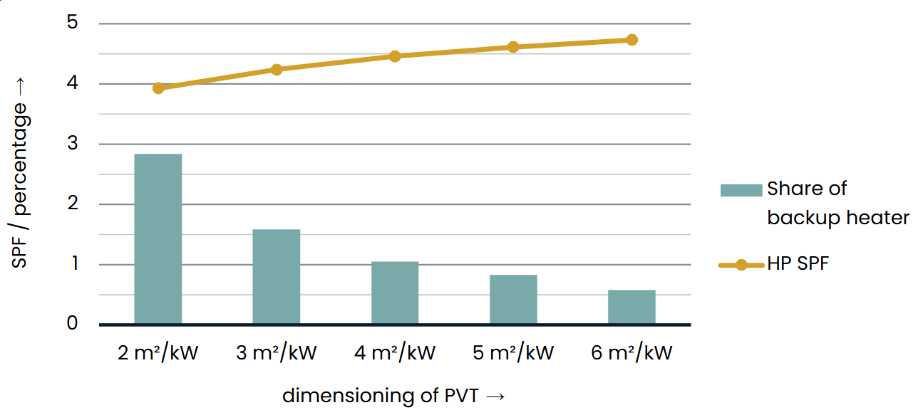
Figure 17: Simulation results for different PVT system sizes (two-family house | Dresden)
With the PVT area reduced by half (2 m²/kW), the heat pump still achieves a seasonal coefficient of performance (SCOP) of just under 4.0. The share of the electric heating element remains below 3%. With 50% more PVT area (6 m²/kW), this share decreases to 0.5%, while the heat pump SCOP increases slightly to 4.75. The recommended guideline value of 4 m²/kW therefore represents a good compromise between investment and operating costs. This value can be adjusted depending on the location, building condition, system components, user comfort requirements, and heat demand. Each building and construction project should be considered as an individual project and designed accordingly. In general, the following applies: A larger PVT system increases overall system efficiency. The reduced electricity demand resulting from the correspondingly higher electricity generation capacity has not yet been taken into account.
As shown by the simulation and measurement data (see figure 15 and figure 17), operation with a smaller PVT system is also feasible, even with the system size reduced by half. Figure 18 hows the monthly measured efficiencies (coefficients of performance, COPs) of a single-family house during the cold winter of 2025/26. The building is equipped with underfloor heating and has a domestic hot water demand with a supply temperature of 50 °C.
The system demonstrates stable and efficient operation, even during the coldest months. In Essen, the average ambient temperature in January was 2.5 °C, with a minimum of −7.5 °C. Nevertheless, a COP of 3.9 was achieved during this month. During the transitional seasons, the COPs were significantly higher. In October, the average temperature in Essen was approximately 11 °C, and the COP reached 4.7.
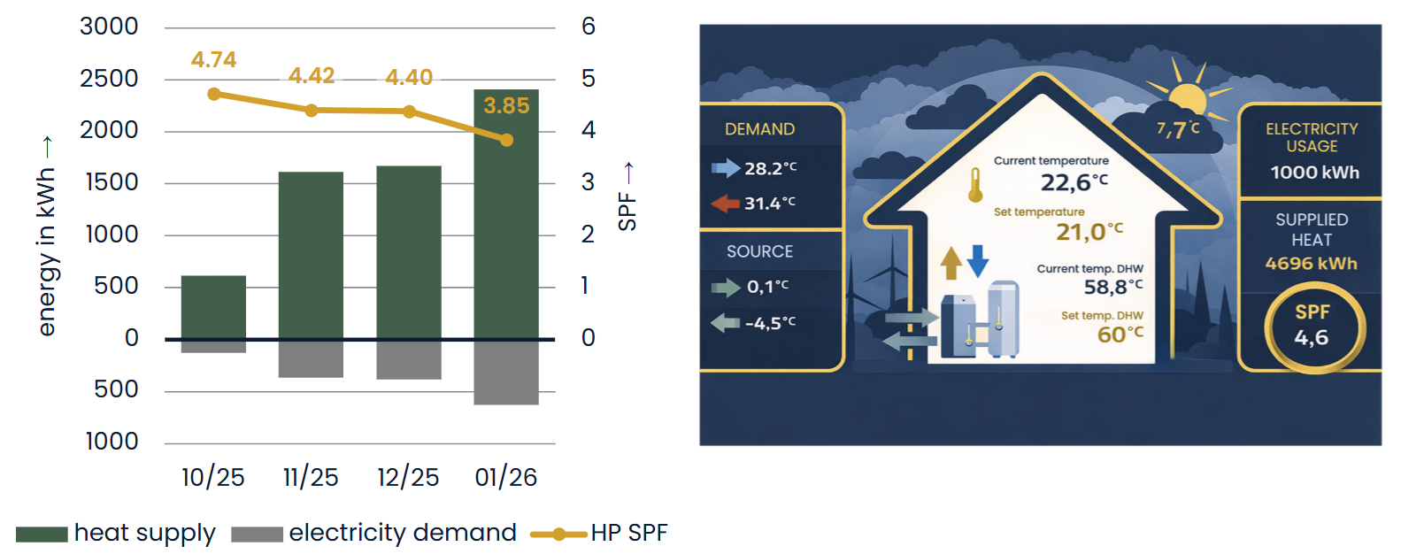
Figure 18: Efficiency of a Small-Scale PVT System in a Single-Family House with Underfloor Heating and Domestic Hot Water | Essen | 2.8 m²/kW
Over the course of the entire year, the seasonal performance factor is significantly higher, as this example only shows the least favorable months of the heating season. By utilizing solar irradiation through the full-surface absorber, such systems benefit particularly during the transitional and summer months. Based on the data presented so far, an annual seasonal performance factor close to 5 is expected for the smaller system sized at 2.8 m²/kW. As described above, a larger system size would further improve this value significantly (also see figure 17).
The simulations presented in figure 17 are based on performance parameters of the Sunmaxx PX-1 module determined through measurements. In accordance with the ISO 9806 collector standard, these parameters were determined by the SPF Institut für Solartechnik. Besides the performance parameters, the module was also tested for durability under extreme conditions. The results independently confirmed the measurements conducted by the Fraunhofer Institute for Solar Energy Systems ISE. The deviations in the performance parameters were minimal (less than 5% depending on the parameter) and do not significantly affect the operation of the PVT module.
Summary
The representative measurement data presented demonstrate that installations using this type of PVT collector can enable efficient heat pump operation throughout the year. Particularly during sunny periods, source temperatures significantly above ambient temperature – by 10 to 15 K – can be achieved, even in winter. During these periods, the PVT system also provides electrical energy to power the heat pump [13]. However, even without solar irradiation, the PVT system can serve as a heat source for a heat pump. Depending on system sizing and ambient conditions, the source temperatures are typically around 2 to 4 K below the ambient temperature. Due to the more efficient heat transfer between brine and refrigerant compared with air and refrigerant, brine-to-water heat pumps can achieve similar efficiencies at these operating points to those of air-to-water heat pumps. During sunny periods, source temperatures – and consequently heat pump efficiencies – are significantly higher, resulting in improved seasonal performance factors [16]. With collectors featuring a flat absorber, complex defrosting cycles are also eliminated. Furthermore, PVT heat pump systems operate quietly and are also suitable for air conditioning and cooling buildings. The area used for the PVT system can therefore provide not only heating but also cooling and electricity.

Literature
[1] D. Sauter, M. Hunziker, M. Schubert, N. Sperr, M. Koch und J. Rohrer, „L-Sol: Heizungssystem mit PVT als Quelle für eine Wärmepumpe,“ Bundesamt für Energie BFE, ZHAW Zürcher Hochschule für Angewandte Wissenschaften, Wädenswil, 2020.
[2] S. Helmling, R. Langner und K. Geimer, „Operational analysis of 5 PVT heat pump systems based on field measurement data,“ in Proceedings of EuroSun 2022 - ISES and IEA SHC International Conference on Solar Energy for Buildings and Industry, Kassel, 2022.
[3] D. Zenhäusern, E. Bamberger und A. Baggenstos, „PVT Wrap-Up. Energiesysteme mit Photovoltaisch-Thermischen Solarkollektoren,“ EnergieSchweiz, Institut für Solartechnik SPF, Bern, 2017.
[4] M. Schubert und D. Zenhäusern, „Performance Assessment of Example PVT-Systems,“ SPF Institute for Solar Technology, IEA SHC TASK 60 | PVT SYSTEMS, Rapperswil, 2020.
[5] A. Baggenstos, S. Büttgenbach, T. Schmidt und D. Zenhäusern, „Einbindung von PVT-Kollektoren in erdsondengekoppelte Wärmepumpensysteme,“ Bundesamt für Energie BFE, 3S Solar Plus AG, SPF Institute for Solar Technology, Bern, 2020.
[6] U. Lester, F. Rudolf und D. N. A. Tjeerd, „Erfolgskontrolle – ZeroEmission-LowExMehrfamilienhaus B35 Zürich,“ Bundesamt für Energie BFE, Hochschule Luzern Technik & Architektur, Luzern, 2014.
[7] C. Binggeli, „Erfolgskontrolle zum Pilotprojekt 2SOL EFH Ersatzneubau, Plattenstrasse 11, Horgen,“ Kanton Zürich, AWEL.
[8] M. Bätschmann, S. Büttgenbach, M. Caflisch und M. Willim, „Erkenntnisse über Erdwärmesonden-Regeneration am Beispiel Doppel-Mehrfamilienhaus Ländisch,“ Allianz 2SOL, Bern, 2021.
[9] M. Bätschmann, I. Bosshard-Mojic, S. Crameri, A. Schmitt, N. Dimri und D. Zenhäusern, „Pilot- und Demonstrationsprojekt Sentmatt Emissionsfreie Wärmeerzeugung mit tiefer Erdwärmesonde, effizienter NiederhubWärmepumpe und optimierter Wärmeverteilung,“ Bundesamt für Energie BFE, Kanton Zürich AWEL, Allianz 2SOL, Halter Immobilien AG, SPF Institut für Solartechnik, Schlieren, 2022.
[10] R. Eismann, C. Messmer, D. Zenhäusern, A. Bohren, F. Sidler und R. Gadola, „CoolShift+: Nächtliche Gebäudekühlung durch natürliche Konvektion und Strahlung mit zeitweiser Unterstützung durch Kältemaschine. Analyse geeigneter Systemkonfigurationen und Modellvalidierung,“ Bundesamt für Energie BFE, Fachhochschule Nordwestschweiz FHNW, Hochschule Luzern HSLU, Ostschweizer Fachhochschule OST, Bern, 2023.
[11] S. Büttgenbach, Nutzung der nächtlichen Abstrahlung zur Gebäudekühlung, Stuttgart: HFT Stuttgart, 2010.
[12] V. Delachaux und M. A. Jaafar, „Experimental Study on Heat Transfer from Ambient Air in Row-installed Photovoltaic-thermal (PVT) Solar Collectors on a Flat Roof,“ in EuroSun 2024: 15th International Conference on Solar Energy for Buildings and Industry, Limassol, 2024.
[13] M. A. Jaafar und B. Chhugani, „Numerical Study of the Effect of the System Specifications on the Performance of a Brine/Water Heat Pump in Combination with Photovoltaic Thermal Solar Collectors,“ in EuroSun 2024: 15th International Conference on Solar Energy for Buildings and Industry, Limassol, 2024.
[14] F. Maag und M. Willi, „Winterstrom maximieren mit schneefreien PVT-Modulen,“ zhaw Züricher Hochschule für angewandte Wissenschaften, Zürich, 2024.
[15] K. Timilsina, B. Chhugani, H. Modi und P. Pärisch, „Dimensioning Method for PVT Collectors as Heat Source of Heat Pumps for Residential Buildings,“ International Sustainable Energy Conference - Proceedings, 2024.
[16] B. Chhugani, P. Pärisch, S. Helmling und F. Giovannetti, „Comparison of PVT - heat pump systems with reference systems for the energy supply of a single-family house,“ Solar Energy Advances, 2023.